|
|
|
1.
|
In the circuit shown above, the value of r for which the current
I is 0.5 ampere is
A. | 1 W | B. | 5 W | C. | 10 W | D. | 20 W | E. | 0 W |
|
|
|
The next three questions relate to the following
circuit diagram, which shows a battery with an internal resistance of 4.0 ohms connected to a 16-ohm
and a 20-ohm resistor in series. The current in the 20-ohm resistor is 0.3
amperes.
|
|
|
2.
|
What is the potential difference across the
terminals X and Y of the battery?
A. | 10.8 V | B. |
6.0 V | C. | 12.0 V | D. | 13.2
V | E. | 1.2 V |
|
|
|
3.
|
What is the emf of the battery?
A. | 1.2 V | B. | 12.0
V | C. | 13.2 V | D. | 10.8
V | E. | 6.0 V |
|
|
|
4.
|
What power is dissipated by the 4-ohm internal
resistance of the battery?
A. | 3.6 W | B. | 0.36
W | C. | 3.2 W | D. | 1.2
W | E. | 4.8 W |
|
|
|
5.
|
Which two
arrangements of resistors shown above have the same resistance between the terminals? A. | II and III | B. | III and IV | C. | I and IV | D. | II and
IV | E. | I
and II |
|
|
|
6.
|
Which of the following is a unit for electrical resistance?
A. | VW–2s | B. | AV–1 | C. | WV–2 | D. | WA–2 |
|
|
|
7.
|
In the circuit shown below, the cell has negligible internal resistance. Which of the following equations is correct? A. | I2 = 2I3 | B. | I3 =
2I1 | C. | I1 = 2I3 | D. | I1 = 2I2 |
|
|
|
8.
|
A conductor of constant resistance dissipates 6.0 W of power when the potential
difference across it is 12 V. The power that will be dissipated in this conductor when the potential
difference across it is 24 V is
A. | 12 W. | B. | 48 W. | C. | 24 W. | D. | 6.0
W. |
|
|
|
9.
|
In the circuit below the battery has emf 6.0 V and negligible internal
resistance. The three resistors each have resistance 10 W. A high
resistance voltmeter is connected as shown. 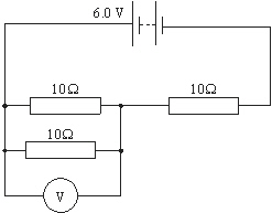 The reading of the voltmeter is A. | 4.0 V. | B. | 6.0 V. | C. | 2.0 V. | D. | 3.0
V. |
|
|
|
10.
|
A capacitor of capacitance C discharges through a
resistor of resistance R. The graph shows the variation with time t of the voltage V across the
capacitor.
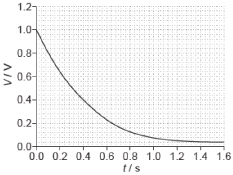
The capacitor is changed to one of value 2C
and the resistor is changed to one of value 2R. Which graph shows the variation with t of V when the
new combination is discharged?
|
|
|
11.
|
Kirchhoff’s laws are applied to the circuit
shown.
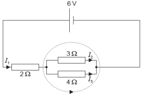
What is the equation for the dotted
loop?
A. | 0 = 3I2 +
4I3 | C. | 6 = 2I1 + 3I2 +
4I3 | B. | 0 =
4I3 - 3I2 | D. | 6 =
3I2 +
4I3 |
|
|
|
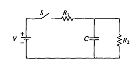 In the circuit shown above, the battery
supplies a constant voltage V when the switch S is closed. The value of the capacitance is C,
and the value of the resistances are R 1 and R 2.
|
|
|
12.
|
Immediately after the switch is closed, the current supplied by the battery
is
A. | V/(R1 + R2) | D. | V(R1 +
R2)/R1R2 | B. | V/R1 | E. | zero | C. | V/R2 |
|
|
|
13.
|
A long time after the switch has been closed, the current supplied by the
battery is
A. | V/(R1 + R2) | D. | V(R1 +
R2)/R1R2 | B. | V/R1 | E. | zero | C. | V/R2 |
|